The restoration of Standedge Tunnel was the most difficult part of the restoration of the Huddersfield Narrow Canal. Some parts of the tunnel were silted up to a depth of six feet. Some sections of the roof had collapsed and others were unstable. Most of the tunnel is only around seven feet wide making access for vehicles and machinery difficult.
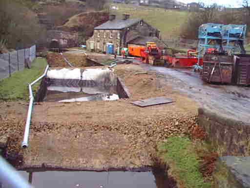
At Marsden portal, a ramp had been built to allow vehicles to run down into the tunnel from this end. Silt was being sucked out through long hoses to each end of the tunnel, from where it was transported away by road.
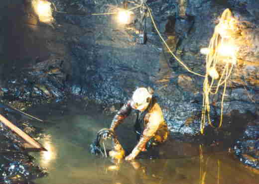
De-silting the canal bed. Photo: British Waterways
Before work to renovate the roof and walls could take place, a huge volume of silt had to be removed. In places the silt was up to six feet deep. (The canal had been constructed deeper than normal in the tunnel as the summit pound acted as a reservoir.)
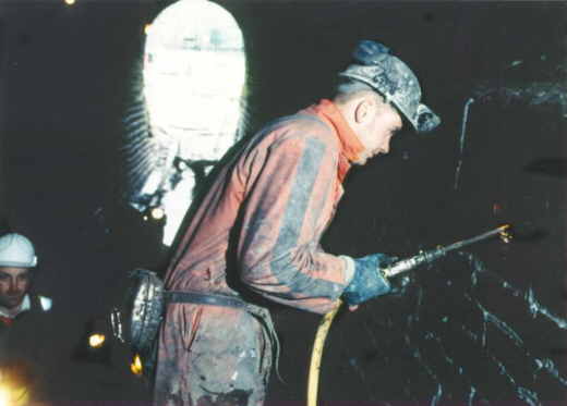
Working on a platform to re-point the side walls. About half of the length of the tunnel is lined with brick or stone. Most of the lined sections were in reasonably good condition and only required re-pointing. Photo: British Waterways
About half of the tunnel was un-lined bare rock. The nature of this varied considerably as the tunnel passes through different rock strata. Some parts are fairly smooth; others very uneven. Some parts were very stable; others were crumbling or loose. At one point, a geological fault had caused a slight shift. In places pieces of rock were in danger of falling.
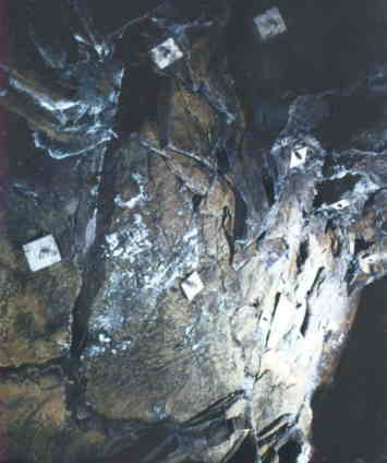
Where there are no small pieces loose, the rock is being stabilised by using rock bolts, like the ones seen in the above picture. Photo: British Waterways
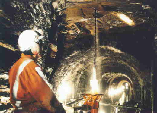
Drilling holes for the rock bolts. Photo: British Waterways
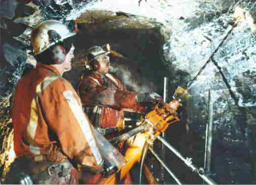
The rock bolts are nearly a metre long. Before each bolt was inserted, a chemical compound was pumped into the hole. This expanded and gripped the bolt in place. The bolts were positioned so that they will prevent any further movement of potentially loose pieces of rock. Photo: British Waterways
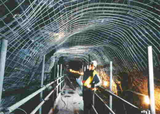
In some of the rock lined sections of tunnel, where the surface was loose, a steel mesh was spread across the roof and walls. Photo: British Waterways
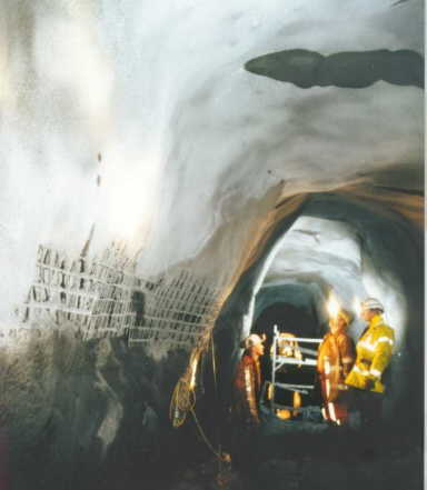
The walls and roof of these sections were then sprayed with a specially formulated concrete. The steel mesh re-inforced the concrete surface. Photo: British Waterways
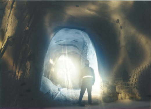
An area which was being spray-concreted, showing the unevenness of some of the wall surfaces. The need to treat the walls has reduced the width of the tunnel in these sections, resulting in a tight fit for boats passing through. Photo: British Waterways